Low-noise phantom microphone supply uses capacitor “trick”
Professional condenser microphones require a 48-V supply to charge the internal capacitive transducer and power the internal buffer for the high-impedance transducer output. You can use a simple boost converter, a filter circuit to reduce electromagnetic interference (EMI), and a little trickery to build a compact, ultra-low-noise, phantom microphone supply (48 V) that operates from a 5-, 12-, or 24-V input. This voltage is often provided by what’s called a “phantom” supply arrangement, which uses the existing microphone connections to deliver power, so no additional supply leads are needed.
(Note that the condenser microphone should not be confused with the electret microphone, which sometimes employs a phantom-power source but of a different kind for its internal preamplifier. If you’re not familiar with the principle and application of phantom power for condenser microphones, see the References at the end for various perspectives.)
This phantom supply is low current, typically only a few milliamps. However, it must be very low noise because the microphone’s output levels are quite low and the microphone buffer doesn’t have very good power-supply ripple rejection. In addition, the phantom microphone supply must not inject EMI into adjacent low-level circuits, which is always a challenge in tightly packed products.
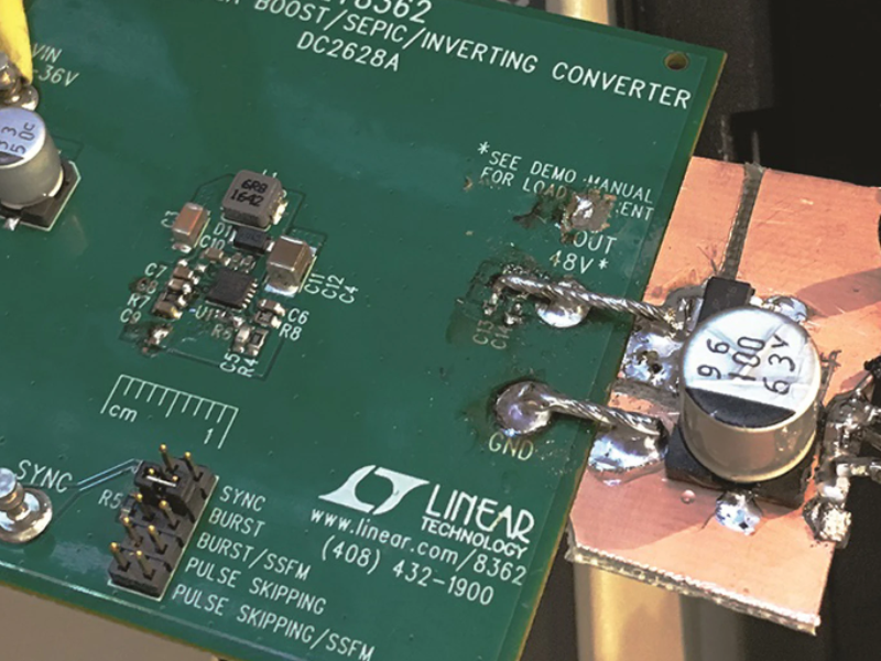
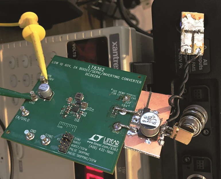
This very high-performance supply is built using the LT8362 boost converter, which features a 60-V, 2-A switch and operation up to 2 MHz, and comes in a package as small as 3 × 3 mm. The circuit is based on the standard LT8362 DC2628A demo board (Fig. 1).
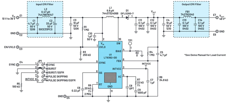
The input EMI filter on the demo board, aided by the switching inductor, does a good job of taking care of high-frequency noise that appears in series with the input. The situation isn’t as good on the output. The output EMI filter effectively suppresses noise in the megahertz region, but it has little effect on noise in the audio range. This noise mostly arises due to the 30X gain in the feedback loop, amplifying the reference noise of the LT8362.
One approach to cure this noise is to add capacitance at the output. Given enough capacitance, this would work. But with a 48-V output, the lowest practical capacitor working voltage of 63 V means that the required capacitors are both big and expensive.
A second approach would be to increase the LT8362 output by a volt or two and add an LDO regulator to the output. This, however, requires a high-voltage LDO regulator, which usually costs more than the low-voltage counterpart. In addition, while these regulators can have low noise at lower output voltages, devices that use a voltage reference also suffer from the same reference-noise multiplication issue as the LT8362.
A third approach is to take advantage of the fact that the sensitivity of the microphone output isn’t highly dependent on the supply voltage, so the phantom supply doesn’t require perfect regulation. This means we can put some resistance in series with the output capacitors to increase their effectiveness; however, it only partly mitigates the size of the high-voltage capacitors.
Instead, a better approach is to make the output capacitors seem bigger than they really are. This can be accomplished with an” old-school” technique called capacitance multiplication, a simple circuit in the gray shaded area of Figure 2.
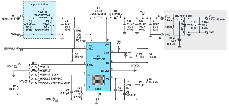
suppresses audio-frequency noise produced by the switching regulator.
Here, the 100-µF capacitor controls the ripple on the base current, so its effect on the collector current is amplified by the beta of the NPN transistor. The effect is dramatic. Figure 3a shows the output of the LT8362 circuit at C4 (before the filter) with a 1-kΩ load (50 mA).

when measured at C4 (before filter) (a). The post-filter output contains a much-improved noise content of just 0.002% (b).
The noise of the microphone supply is roughly 80 mV p-p, which represents about 0.2% noise content. While this may be sufficient for noncritical applications, the output after the filter is substantially better at approximately 1 mV p-p (Fig. 3b). This represents about 0.002% or 20-ppm noise content, which is sufficiently low for even the most demanding applications. Figure 4 shows the benchtop setup.
The SBCP56-16T1G transistor was chosen for its high VCBEO (80 V) and high beta at low currents. The high beta gives the capacitance multiplier its high apparent capacitance and relatively constant drop as output current varies. The output voltage drops from 47.8 V with a 2-kΩ load to 47.5 V at 500-Ω load, which is sufficient for microphone applications. Don’t substitute another transistor without testing for noise and regulation.
The tests were run with 16-V input, but the performance will be similar with 12 V to 24 VIN. Some applications may require boosting from 5 V, which can be accomplished by decreasing the LT8362’s switching frequency from 2 MHz to 1 MHz to allow for the 75-ns minimum off time. This would also require increasing L1 to about 10 µH to 15 µH and doubling up on bulk-output capacitor C4 to maintain equivalent performance.
Thomas Mosteller was a Field Applications Engineer for Analog Devices’s Mid-Atlantic region starting in 1990, and Christopher Jarboe is an Applications Engineer at Analog Devices.
Related articles:
Raspberry Pi gets advanced voice codec capability
 If you enjoyed this article, you will like the following ones: don't miss them by subscribing to :